
Your shopping cart is empty! Please select the type which you want.
Home > Industry information > 5Kw Isolated Bidirectional DC-DC Converter Solution
5kW Isolated Bidirectional DC-DC Converter Solution
Customized industrial electronic application solutions by the professional development team at Optocoupler Network!
The 5kW isolated bidirectional DC-DC converter is capable of delivering up to 5kW of power. It takes voltage from the high side and outputs voltage to the low side, or takes voltage from the low side and outputs voltage to the high side. This power supply employs the Dual Active Bridge (DAB) method, emphasizing efficiency. The DAB method features a full bridge configuration onboth the high side and low side, allowing for handling higher power compared to the half bridge method. Additionally, by implementing phase shifting for power transfer, soft switching is achieved, resulting in a highly efficient DC-DC converter. This solution can be applied in various industrial equipment, as well as electric vehicle (EV) charging systems and photovoltaic power inverters.
Solution Overview
Assuming a high side input/output of 750V, the devices must withstand a switching voltage of 1000V or higher, making IGBTs a common choice. However, when using IGBTs, significant switching losses are expected, so there is no anticipated improvement. This power supply utilizes the 1200V SiC MOSFET TW070J120B for high-power conversion and high efficiency. On the low side, assuming an input/output of 400V, the TK49N65W5 is a 650V MOSFET that achieves high efficiency due to its superjunction structure and integrated high-speed diode, reducing switching losses. When switching the 1200V SiC MOSFET, the gate driver has a 4A current drive capability to adequately drive gate charge and discharge currents. The intelligent gate driver coupler TLP5214A, with overcurrent protection and UVLO functionality, is coupled with a voltage sensing circuit using the optocoupler TLP7920, which offers high linearity accuracy and high common-mode transient immunity.

Side view of 5kW isolated bidirectional DC-DC converter
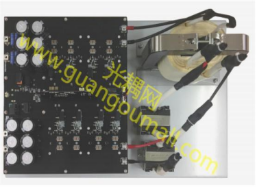
Top view of 5kW isolated bidirectional DC-DC converter

Simple diagram

Efficiency curve
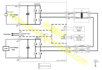
wiring diagram
Precautions: (To prevent electric shock, burns, etc.)
When connecting to a stable power source, be careful of electric shock. Do not directly touch each part of the power source when it is energized. Be extremely careful when observing waveforms. Even after the power source is turned off, there is still a risk of electric shock due to residual charges in various capacitors. Before touching the circuit board, make sure that the voltage of each part has sufficiently decreased. In addition, the semiconductors or inductors of the power source generate heat according to the load current. Do not touch any part of the power source while it is operating, as there is a risk of burns.
1. Bidirectional power flow: This converter can achieve the conversion of electrical energy between two directions, i.e., it can deliver DC power from one energy source to another energy load, or feedback the DC power generated on the energy load back to the energy source.
2. High efficiency: Bidirectional DC converters typically have high conversion efficiency, minimizing energy losses. Overall efficiency: 97% (conditions: Vin = 750V, 100% load).
3. High power density: A 5kW converter has a large power, but isolated bidirectional DC converters usually have high power density, relatively small volume, and are suitable for applications with limited space.
4. Safety isolation: Isolated bidirectional DC converters can provide electrical isolation, completely isolating the input and output ends, thereby improving system safety and reliability.
5. Wide input-output voltage range: Bidirectional DC converters usually have a wide input-output voltage range to accommodate different application requirements.
6. Small size, compact dimensions: 565mm×360mm×270mm.
parameter
Parameter | Condition | Minimum | Typical | Max | Unit |
Input/output characteristics | |||||
High side voltage | During the input operation | 732 | 750 | 768 | V |
Low side voltage | During the output operation
| 396 | 400 | 404 | V |
Low voltage current measurement | During the output operation
| 13 | A | ||
rated power | 5 | KW | |||
switching frequency | 50 | KHZ |
This solution describes how to design various circuits for a 5kW isolated bidirectional DC-DC converter (hereinafter referred to as the power supply). Please refer to the reference Guide for the specifications, usage, and characteristics of the power supply. Even if the part number is shown in the circuit diagram, if it is shown as "not installed" in the bill of materials, it is not installed on the pcb. A mounting position is provided on the PCB for constant value adjustment during circuit design
Application Fields
A 5kW isolated bidirectional DC-DC converter is a high-power electronic device that enables energy conversion between two different voltage levels of DC power sources, and allows energy flow in both directions. This type of converter is commonly used in the following applications:
1. Electric Vehicles (EVs) and Plug-in Hybrid Electric Vehicles (PHEVs): In the energy management system of electric vehicles, a 5kW bidirectional DC-DC converter is used for energy transfer between the high-voltage battery pack and the low-voltage auxiliary battery. They can also enable bidirectional charging and discharging between the vehicle and the grid, supporting Vehicle-to-Grid (V2G) and Grid-to-Vehicle (G2V) applications.
2. Energy Storage Systems: In solar photovoltaic or wind energy systems, this converter can be used to transfer electric energy generated by renewable sources between energy storage units, optimizing energy usage and storage.
3. Grid Ancillary Services: Bidirectional DC-DC converters play an important role in grid ancillary services such as demand response and frequency regulation, helping balance supply and demand and improving grid stability.
4. Industrial Applications: In industrial processes that require large-scale DC power transmission, such as electroplating, electrolysis, or any application that requires precise DC power supply.
5. Backup Power Systems: For example, in uninterruptible power supply (UPS) systems in data centers or critical facilities, to ensure continuous power supply in the event of a main power failure.
6. Aviation and Maritime Applications: Used for energy conversion and distribution between electrical systems in aircraft, ships, and other transportation vehicles.
Due to its ability to handle high power levels, a 5kW isolated bidirectional DC-DC converter is crucial for applications that require efficient, reliable, and flexible power management. The isolated design also provides additional safety by protecting users and sensitive electronic devices through electrical isolation.
High voltage section circuit (higher voltage end)

High voltage section circuit diagram
Low voltage section circuit (higher and lower voltage ends)
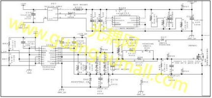
Gate drive circuit (lower voltage side lower arm) diagram
This describes one of the gate drive circuits on the low voltage side. The gate drive circuit design can affect power efficiency and EMI noise. Typically, there is a trade-off between power efficiency and EMI noise, so the design needs to be balanced. The gate drive circuit of this power supply has a circuit configuration that can adjust the MOSFET switching speed. If it is necessary to reduce the noise during MOSFET conduction, increasing the gate series resistance (R88) to a larger value may reduce EMI noise. It should be noted that if the gate series resistance value becomes larger, not only the conduction speed of the MOSFET will decrease, but also the turn-off speed will decrease, which may lead to a decrease in power efficiency. In this case, in order to reduce the decrease in power efficiency, only the turn-off speed of the MOSFET should be increased. Decreasing the gate series resistance (R86) may only increase the turn-off speed of the MOSFET and reduce the decrease in system power efficiency. When changing the gate series resistance, it is necessary to confirm that it meets the required EMI noise, power efficiency performance, and heat dissipation
performance of the system.
Critical device
Device type | Device catalog | Loading position. Quantity | Description |
TW070J120B | Power SiC MOSFET | High voltage side switch.4 | N Channel SiC MOSFET, 1200V, 0.07Ω(typical value)@20V.TO-3P(N), 2nd generation |
TK49N65W5 | Power MOSFET (N channel 500V<VDSS≤700V) | Low voltage side switch.4 | N Channel MOSFET, 650V, 0.057Ω@10V,TO-247,DTMOSIV |
TLP5214A | Intelligent grid drive IC | gate drive.8 | Optocoupler (photoelectric IC output), IGBT driver IC, IOP=+/-4.0A,5000Vrms, SO16L |
TLP7920 | isolation amplifier | voltage detection.2 | Optocoupler (isolation amplifier), analog output, 5000Vrms, DIP8 |
service and support
● Overall solution: Provide a complete inverter solution to meet customer requirements, with customization and optimization according to customer needs.
● PCB: Provide PCB boards, PCB manufacturing files, stencil files, printing files, and layout files. Ensure reasonable layout and stable wiring. Customers can make secondary development and layout adjustments according to their own needs.
● Selection of power MOSFETs, gate drivers, and isolation amplifiers: Provide selection recommendations for power MOSFETs, gate drivers, and isolation amplifiers, and assist customers in obtaining product parameters and usage guidelines.
● Relevant design reference literature: IC design documents, circuit topologies, design principle analysis, major component selection rules, and industry-related regulations.
● BOM (Bill of Materials) optimization: Provide BOM optimization based on customer requirements to ensure reliable component quality.
Device introduction
TK49N65W5
Features:
● Fast reverse recovery time: trr = 145 ns (typical value)
● Low leakage source on-resistance: RDS(ON) = 0.051 Ω (typical), utilizing super junction structure: DTMOS
● Easily controllable gate switch
● Enhancement mode: VTH = 3 to 4.5V (VDS = 10V, ID = 2.5 mA)
TLP5214A
Features:
● Peak output current: ±4.0A (max)
● Guaranteed performance across the entire temperature range: -40 to 110 ℃
● Supply current: 3.8 mA (max)
● Supply voltage: 15V to 30V
● Threshold input current: 6mA (max)
● Propagation delay time: 150ns (max)
● DESAT leading edge blanking time: 1.1 us (typ.)
● Common-mode transient immunity: ±35 kV/us (min)
● Isolation voltage: 5000 Vms (min)
TLP7920
Features:
● Output side supply voltage: 3.0 to 5.5 V
● Output side supply current: 6.2 mA (typical)
● Operating temperature range: -40 to 105 °C
● Common-mode transient immunity: 15 kV/us (minimum)
TW070J120B
peculiarity
● Second generation chip design (built-in SiC Schottky barrier diode)
● Low diode forward voltage: VDSF =-1.35V (typ.)
● High voltage: VDSS =1200 V
● Low drain-source on-resistance: RDS(ON) =70 m2 (typ.)
● High threshold voltage, not easy to fail; Vn=4.2 to 5.8V (VDS=10 V, ID=20 mA)
● Enhanced mode
Industry information
