
Your shopping cart is empty! Please select the type which you want.
Home > Message box > 100W LED Lighting Power Supply Development Solution
100W LED Lighting Power Supply Development Solution
The 100W LED lighting power supply is a constant current power device that is compatible with AC inputs ranging from 90 to 264 volts. It can convert AC power into a typical output of 1.04 amperes of direct current, with a maximum power capacity of 100 watts. This solution provides various design information to help reduce the time required for design based on actual specifications.
Solution Overview
The solution also mentions the DTMOS series products, which are suitable for power factor correction (PFC) circuits and flyback circuit switch elements in switch mode power supply applications, thereby reducing losses (steady-state losses) caused by MOSFET on-resistance and switching losses. These products can achieve a conversion efficiency of 90%. The MOSFETs are designed with insulation packaging, eliminating the need for additional insulation sheets when mounting heat sinks, making it more convenient during circuit board assembly. The universal PFC inductor, flyback transformer, input/output capacitors, etc. all use a housing size of 180mm x 57mm x 40mm, providing greater flexibility for design applications.

picture of real products
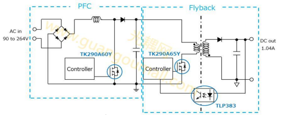
Simple block diagram
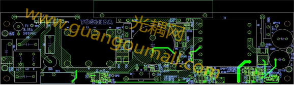
layer1
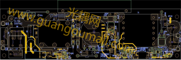
layer2

High temperature power generation technology and fields
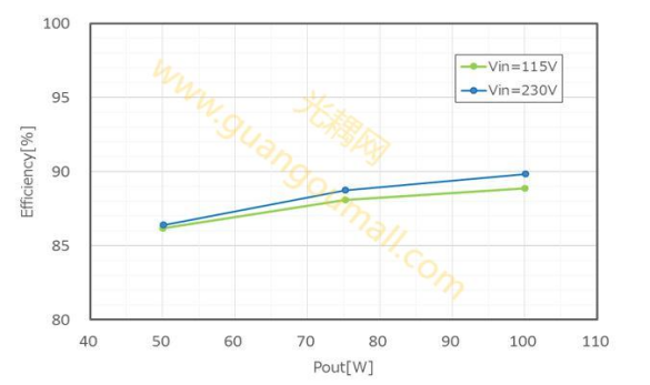
Benefit curve
Parameter
Parameter | Condition | Min | typical value | Max
| Unit |
input characteristics | |||||
Ac input voltage (RMS) | 90 | 264 | V | ||
Ac input current (Vin=90V, Pout=100W) | 1.4 | A | |||
Ac input frequency | 47 | 63 | Hz | ||
output characteristics | |||||
output voltage | 110 | V | |||
current output | 0.99 | 1.04 | 1.09 | A | |
output power | 50 | 100 | W |
Power Factor Correction (PFC) Circuit Design
To improve power factor, the Texas Instruments' key mode PFC controller UCC28051 (PFC controller) is used for PFC circuit design. The following diagram illustrates the PFC circuit (PFC controller - peripheral devices) and explains the basic design approach. For detailed peripheral design information, please refer to the UCC28051 datasheet, related documents, etc.
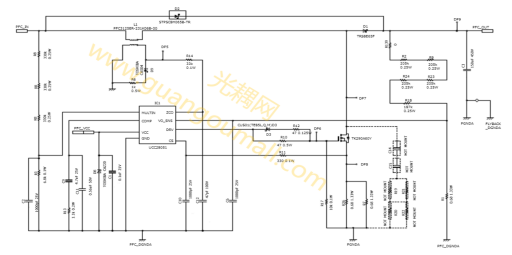
PFC Circuit (PFC Controller)

Output voltage setting circuit
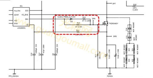
Grid drive circuit
Gate drive design can affect both power efficiency and Electromagnetic Interference (EMI), also known as noise. Typically, there is a trade-off between power efficiency and EMI (noise), so a balanced design is required. To reduce EMI (noise), it is recommended to increase the resistance value of the gate series resistors (R10, R12). The turn-on and turn-off speeds of the MOSFET can be adjusted separately in the gate drive circuit, but if EMI (noise) is generated during the turn-on or turn-off process, it is not necessary to change the resistance values of all gate series resistors. To increase the turn-on time, the resistance value of R10 can be increased, and to increase the turn-off time, the resistance value of R12 can be increased. Please note that increasing the value of resistors (R10, R12) will slow down the switching speed of the MOSFET, which may lead to a decrease in power efficiency. It is necessary to check whether the power efficiency specifications and thermal specifications meet the required standards.

Constant current circuit design
Texas Instruments' flyback controller UCC28060 (flyback controller) is used to implement a 100 watt constant current circuit. The basic design method is illustrated by the figure above, which shows the constant current circuit (flyback controller periphery). For detailed peripheral design, please refer to the UCC28060 data manual, related documents, etc.
Features:
1. LLC Resonant Circuit: The power supply utilizes the LLC resonant circuit method, effectively controlling the output voltage by alternately switching the high-side and low-side MOSFETs on the primary side (with a 50% duty cycle), and adjusting the switching frequency based on the load to maintain the desired output voltage.
2. Zero Voltage Switching (ZVS): ZVS occurs during the switching process, significantly reducing switching losses. ZVS is a feature that allows the power supply to achieve high efficiency by minimizing energy waste during MOSFET transition states.
3. High-Efficiency Power Supply: Due to ZVS and resonant operation, the power supply is designed for high efficiency, reducing energy consumption and improving performance, which is crucial for LED lighting applications where efficiency is a key consideration.
4. Electromagnetic Interference (EMI) Considerations: The design of the gate drive circuit takes into account the trade-off between power efficiency and electromagnetic interference (EMI). Due to ZVS operation, the LLC circuit is configured to have low EMI. If EMI is still a concern, the design allows for adjustment of resistor values to fine-tune MOSFET switching and minimize noise, providing flexibility in managing EMI issues.
5. Texas Instruments Controller: The power supply design incorporates a controller from Texas Instruments, which is renowned for its reliability and performance in power management applications. This controller helps form the LLC resonator, ensuring stable operation and control of the power supply.The combination of these design features results in an efficient, reliable power supply that minimizes losses and EMI, which is crucial for high-performance LED lighting systems.
Critical device
Device type | Device catalog | Loading position ・quantity | description |
TK290A60Y | Power MOSFET (N channel 500V < VDSS≤700V) | PFC・1 | N Channel MOSFET, 600V, 0.29Ω@10V, TO-220SIS, DTMOSⅤ |
TK290A65Y | Power MOSFET (N channel 500V < VDSS≤700V) | primary side・1 | N Channel MOSFET,600V,0.29Ω@10V,TO-220SIS,DTMOSⅤ |
TLP383 | optocoupler | Output voltage feedback・1 | Optocoupler (phototransistor output), DC input, 5000Vrms, 4pin SO6L |
Device selection replacement
We carefully select replacement chips for your products, in order to provide more cost effective, better performance, more stable supply, and better technical support chip solutions to meet the needs of customers in the changing market.
Replacement device model | brand | Original type | Original type |
SL11N65CF | SLKOR | TK290A65Y | The power is slightly lower |
K10101C | COSMO | TLP383 | direct substitution |
K10101B | COSMO | TLP383 | direct substitution |
VOL617A-3X001T | VISHAY | TLP383 | direct substitution |
AC-side circuit
EMI suppression components
The common mode choke (L2) is used to suppress common mode noise. In addition, X capacitors (C4, C8) are used to prevent differential mode noise. Since each noise level is influenced by PCB layout and enclosure structure, the above components may need to be modified, removed, or added as needed. Since this power supply does not have an enclosure, Y capacitors are not installed. However, when designing systems with enclosures, Y capacitors should be installed as a countermeasure against common mode noise. Please note that when installing Y capacitors,
if the capacitance value increases, the leakage current will also increase. Therefore, please confirm that safety standards are met.
Components for suppressing surge current
The resistor (R15) and relay (RY1) are used to suppress surge current when the AC power supply is turned on. When the AC power supply is turned on, the relay (RY1) is open, and the AC line current flows through the resistor (R15), thereby suppressing surge current. After the AC power supply is turned on, the main 12V power supply from the external power source is detected, and the relay (RY1) becomes conductive. Once the relay (RY1) is conductive, the resistor (R15) is shorted, reducing power loss during operation. It is necessary to select a resistor (R15) that can withstand surge current. Also, check the opening conditions and time, as well as the continuity of the relay (RY1), to ensure that the required specifications are met.
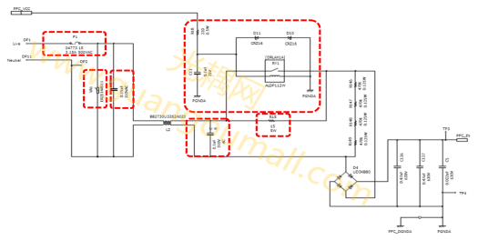
AC side circuit
On-board Power MOSFET Selection
This power supply will be used in lighting fixtures that require more light, such as commercial facilities. The typical configuration for this lighting is that the power unit is separate from the light bulb, so there is no need to reduce the thickness of the power unit to integrate it into the bulb. In home lighting, heat dissipation may be a concern, but considering the convenience of heat sink assembly, we have chosen a perforated insulation package that does not require an insulating sheet and can be directly mounted on a heat sink. This power supply, with a design value of 390 volts, provides a constant DC output of 1.04 amps for PFC and flyback circuits. The reasons for selecting MOSFETs for the PFC and flyback circuits are explained below.
MOSFET for PFC
The PFC output voltage is 390 volts. A component with a maximum rating of 600 volts was selected, taking into account the voltage peak caused by the voltage surge effect of the inductive components during MOSFET switching. The losses caused by the MOSFET have a steady-state loss, which is determined by the on-resistance and the switching current of the MOSFET. Typically, when selecting a MOSFET with a lower on-resistance, the steady-state loss decreases, but there is a trade-off relationship with the switching loss, which increases. The input current of the PFC circuit of this power supply is maximum when the input voltage is at its lowest. When the input voltage is AC 90 volts and the output power is 100 watts, the input current (RMS value) is approximately 1.34 amps within the operating range. Therefore, the TK290A60Y was chosen because it has a maximum on-resistance of 0.29 ohms, with a focus on reducing switching losses.
MOSFET for Flyback
The PFC output voltage of 390 volts is the input voltage for the flyback circuit. After adding approximately 100 volts of flyback voltage to this 390 volts, it is applied to the MOSFET. A component with a maximum rating of 650 volts was selected, considering the voltage surge caused by the inductive components of the circuit board and wiring during switching, as well as the derating relative to the maximum rated voltage of the MOSFET. When the output power reaches its maximum, i.e., 100 watts, the input current of the flyback circuit is maximum. At this time, the input current is approximately 0.3 amps, so the TK290A65Y was chosen, which has an on-resistance of 0.29 ohms (maximum), with a focus on reducing switching losses, just like in the PFC circuit.
Services and Support
● Overall solutions: Provide complete LED lighting power supply solutions to meet customer requirements and customize and optimize them according to customer needs.
● PCB: Provide PCB boards, PCB manufacturing files, stencil files, printing files, and layout files. Ensure reasonable layout and stable wiring. Customers can perform secondary development and layout adjustments according to their own needs.
● Power MOSFET and Optocoupler Selection: Provide selection advice for power MOSFETs and optocouplers, and assist customers in obtaining product parameters and usage guides.
● Relevant Design Reference Literature: IC design documents, circuit topologies, design principle analysis, major component selection rules, and industry-specific regulations.
● Bill of Materials (BOM) Optimization: Provide BOM optimization based on customer requirements to ensure reliable component quality.
Device introduction
● For PFC circuit
●V_DSS = 600 V
● R_DS(ON) (Max value) = 0.29Ω@V_GS = 10V,
●TO-220SIS Package (TO-220 insulation package)
● Adopt superstructure design to achieve both high voltage resistance and low on-resistance
TK290A65Y
● For flyback circuit
● V_DSS = 650 V
● R_DS(ON) (Max value) = 0.29Ω@V_GS = 10V
● TO-220SIS Package (TO-220 insulation package)
● Adopt superstructure design to achieve both high voltage resistance and low on-resistance
TLP383
● Collector-emitter voltage: 80 V (Min value)
● Current transmission ratio: 50% (Min value)
●GB rating: 100% (Min value)
● Isolation voltage: 5000 Vrms (Min value)
● Operating temperature range: -55 to 125°C
● Programmable Logic Controller (PLC)
● AC adapter
● Input/output interface board
Message box
