
Your shopping cart is empty! Please select the type which you want.
Home > Message box > Development Solution For Sensorless Sinusoidal Brushless Motor Drive Circuit Using TC78B011FTG
Development solution for sensorless sinusoidal brushless motor drive circuit using TC78B011FTG
Solution Overview
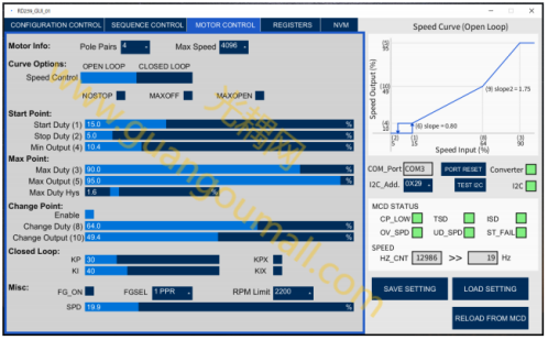
This solution describes a reference design for a sensorless sinusoidal brushless motor drive circuit using TC78B011FTG. With the increasing use of brushless motors in various applications, there is a growing demand for stable brushless motor control with less noise and customizable speed curves. This design is based on Toshiba's TC78B011FTG (referred to as MCD, Motor Control Driver), which is a three-phase PWM chopper pre-driver that operates brushless motors using a sensorless sinusoidal control method. Sinusoidal motor drive control results in less noise and vibration during motor operation. It also provides closed-loop motor speed control without the need for an external microcontroller, enabling more stable motor speed control. The speed curve can be precisely set in the MCD to achieve precise motor control. Motor control settings are done through I2C communication in the MCD registers. Once these settings are done, the motor can be controlled by influencing external signals that affect motor speed, direction, braking, etc. Motor control speed can be controlled using three different methods, including PWM, analog voltage, and I2C. The motor control settings in the MCD registers can be stored in its internal non-volatile memory (NVM) and loaded on the next startup of the MCD. Therefore, stable motor control can be achieved through simple settings without the need for an external microcontroller. This design also uses Toshiba's TPHR1204PB power MOSFETs to drive the brushless motor and TCR1H5F0B low dropout linear regulator (LDO) to generate a 5V power supply. We have also developed a graphical user interface (GUI) to easily perform the MCD register settings through I2C communication. For communication, a USB-I2C converter is used between the GUI on the PC and the circuit board (PCB) of this design. Applications of this design include fans, blowers, pumps, vacuum cleaners, etc.
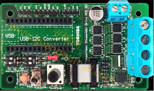
picture of real products
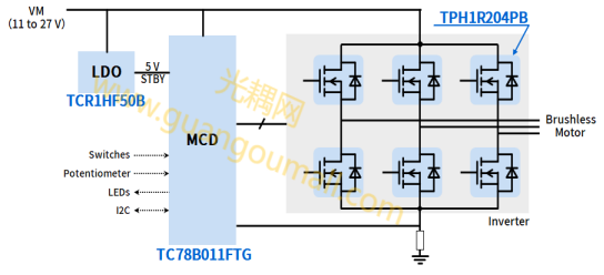
Sample block diagram
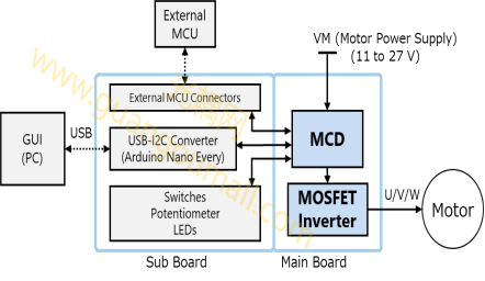
The image above shows the complete system configuration of this design, including the motherboard and the child board. This simple design makes it easy to drive brushless motors with a non-inductive sine wave method.
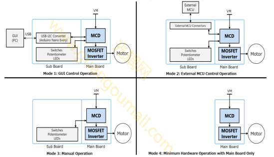
This design can operate in multiple modes, as shown in the figure above. The descriptions of each mode are as follows:
- Mode 1 allows users to control the motor using a graphical user interface or a sub-board.
- Mode 2 allows users to control the motor using an external microcontroller or a sub-board.
- Mode 3 allows users to control the motor using only the sub-board, without any external connections.
- Mode 4 allows users to run the motor using only the main board, indicating that the TC78B011FTG can operate brushless motors with very minimal hardware requirements.
Parameter
Items | Specification |
Input supply voltage | Dc 11 to 27V |
Input control signal voltage | Dc 5V |
Rated input current | 20A(Max) |
Drive motor type | Brushless electric machine |
Motor control type | Non-inductive sine wave drive |
MCD setting mode | l2C |
Main motor control models | Brake, direction, speed signal |
Board size | 90X50mm |
Motherboard size 39X50mm | |
Board layer configuration | 4-layer through hole (outer layer 35μm ,inner layer 70μm ) |
Design specification parameter
Items | Specification |
GUI platform | Processing(4.2) |
Library used | ControlP5(2.2.6) |
PC operating system | Windows 10 |
Board size | 90X50mm |
Graphical User interface (GUI) Main specification parameters
Items | Specification |
hardware | Arduino Nano Every |
Software development environment | Arduino Windows application program (1.8.19) |
Library used | Wire.h |
PC operating system | Windows 10 |
USB-I2C converter specifications
Power Supply Circuit for Motor
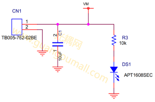
The motor power supply (VM) is the main power source in this design, which is connected through the motor power input connector CN1. This power is directly supplied to the TC78B011FTG motor pre-driver IC, and further inputted to the inverter circuit consisting of TPHR1204PB MOSFETs. The diagram below shows the VM power input circuit. When the VM power supply is available, the orange LED (DS1) will light up. The VM input voltage range is 11 to 27 volts.
VM power input circuit
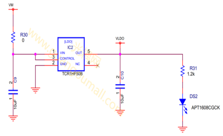
A VLDO voltage of 5 volts is required to pull up various signals in the design, such as STBY, SPD, etc. This 5 volt VLDO voltage is generated by the TCR1H5F0B LDO, using VM as the input voltage, as shown below. The TCR1H5F0B LDO supports a wide input voltage range from 4 to 36 volts, which is ideal for this design as the input voltage VM ranges from 11 to 27 volts. When the VLDO power supply is available, the green LED (DS2) lights up
Inverter Circuit
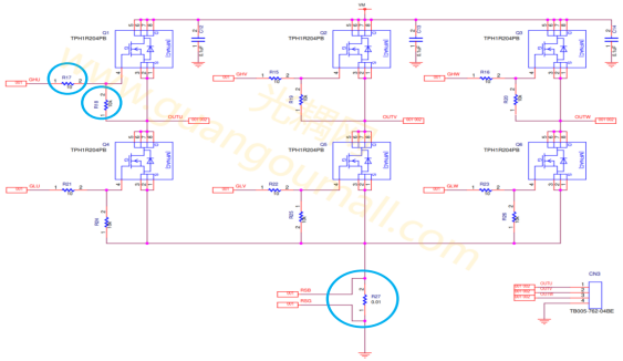
The inverter circuit is used to drive a three-phase brushless motor and is powered by a DC power supply (VM). Six high-speed TPHR1204PB MOSFETs are used as the switching devices in the inverter. These MOSFETs are controlled by the TC78B011FTG. The inverter circuit for this design is shown in the diagram below. Pull-down resistors, such as R18, are used between the gate and source of each MOSFET to turn off the MOSFET when the gate signal is low. Series resistors, like R17, are used to control the charging and discharging rate of the MOSFET, thereby affecting the MOSFET's turn-on and turn-off time. Therefore, these series resistors can be adjusted based on the desired application to fine-tune the MOSFET's turn-on and turn-off time. A shunt resistor, R27, is used to monitor the total current between the inverter and the motor. This current is calculated by measuring the voltage difference across the shunt resistor R27 (using Kelvin connections with the RSB and RSG signals) through the TC78B011FTG.
Wiring design
Kelvin connection for sensing current
Kelvin connections are used to reliably measure the voltage difference across the electrical flu-measuring shunt resistor R27. The TC78B011FTG uses specialized RSB and RSG inputs to sense motor current. The routing patterns for the shunt resistor R27 and the RSB and RSG inputs are shown in the figure below.
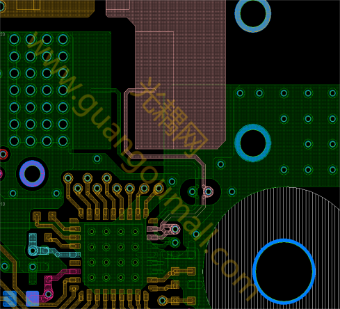
Current sensing Kelvin connection circuit
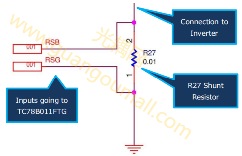
Sensing current Kelvin connection circuit (schematic)
Features
1. Sinusoidal drive: The TC78B011FTG MCD (Motor Control Driver) uses sinusoidal drive method, which helps reduce noise and vibration during operation.
2. Sensorless PWM drive: This design implements sensorless PWM drive, eliminating the need for external sensors to detect the position of the motor rotor, simplifying the design and reducing costs.
3. Wide operating voltage range: The TC78B011FTG supports an operating voltage range from 5.5 to 27 volts, with an absolute maximum rating of 30 volts.
4. Pre-drivers for high-side and low-side N-channel MOSFETs: Suitable for both high-side and low-side N-channel MOSFETs, providing flexible driving options.
5. Built-in closed-loop speed control: Features built-in closed-loop speed control with adjustable speed curves, enabling stable motor speed control without the need for an external microcontroller.
6. Multiple control methods: Supports motor speed control using analog voltage, PWM duty cycle, or I2C.
7. I2C serial interface: Convenient I2C communication interface for various settings, enhancing design flexibility.
8. Rich built-in protection and monitoring features: Includes thermal shutdown, undervoltage lockout, charge pump low voltage detection, output current limit, overcurrent detection, and lock protection.
9. Compact QFN36 package: Compact package makes it suitable for space-constrained applications.
10. Versatile applications: Suitable for various devices such as server fans, blowers, pumps, vacuum cleaners, and more.
These features and advantages make the TC78B011FTG an efficient, reliable, and versatile motor drive solution for a wide range of applications.
Device type | Device catalog | Loading position ・ quantity | Description |
TC78B011FTG | Brushless motor driver IC | Mainboard ・1 | Sensorless sine wave pwm pre-driver for three-phase brushless motors |
TPH1R204PB | Power MOSFET (N-channel, single type, 30V < VDSS ≤ 60V)
| Mainboard ・6 | N Channel MOSFET, 40 V, 0.0012Ω@10 V, SOP Advance, U-MOS-H |
TCR1HF50B | Low dropout (LDO) linear regulator | Mainboard ・1 | High voltage, low static current, fast load transient CMOS linear regulator |
Services and Support
● Overall Solution: Provide a complete brushless motor driver solution to meet customer requirements, with customization and optimization based on customer needs.
● PCB: Provide PCB boards, PCB manufacturing files, stencil files, printing files, and layout files. Ensure proper layout and stable wiring. Customers can perform secondary development and layout adjustments according to their own needs.
● Selection of Power MOSFET and Brushless Motor Driver IC: Provide recommendations for power MOSFET and brushless motor driver IC selection and assist customers in obtaining product parameters and usage guidelines.
● Relevant Design Reference Materials: IC design documents, circuit topologies, design principles analysis, major component selection rules, and industry-related regulations.
● Bill of Materials (BOM): Provide BOM according to customer requirements to ensure reliable component quality.
Component Introduction
Brushless Motor Pre-Driver TC78B011FTG
This design uses the TC78B011FTG MCD to drive a brushless motor through an inverter circuit.
Features:
● Sinusoidal drive
● Sensorless PWM drive
● Capable of driving Delta or Wye-configured motors
● Operating volta
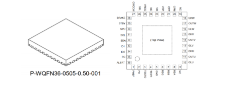
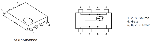
Power MOSFET TPH1R204PB
This design uses the TPH1R204PB MOSFET in an inverter circuit, for driving a brushless motor.
Features:
● High-speed switching
● Small gate charge: Qsw = 21 nC (typical)
● Small output charge: Qoss = 56 nC (typical)
● Low on-resistance: Rds(on) = 0.85 mΩ (typical, Vgs = 10 V)
● Low leakage current: Idss = 10 μA (max, Vds = 40 V)
● Enhancement mode: Vth = 2.0 to 3.0 V (Vds = 10 V, Id = 0.5 mA)
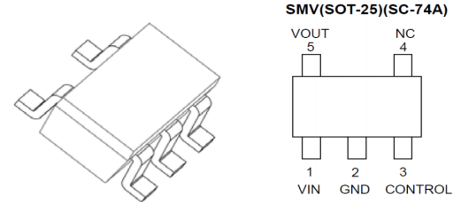
TCR1H5F0B
This design uses the TCR1H5F0B as a 5V regulator.
Features:
● High input voltage: 40V (absolute maximum rating), 4V to 36V (operating input voltage)
● Low quiescent current: I_BON = 1μA (typical) @ I_OUT = 0mA
● High response load transient: -60mV / +50mV, I_OUT = 0mA ≈ 10mA
● Output voltage: V_OUT = 5.0V
● High accuracy output voltage: ±1% (ambient temperature 25°C)
● Overcurrent protection
● Thermal shutdown
● Reduced inrush current
● Pull-up connection between CONTROL and VIN
● Can use ceramic capacitors
● General-purpose package: SMV (SOT-25) (2.8mm x 2.9mm x 1.1mm)
Message box
